|
We have created a set on links here to the entries in our Glossary
Of Terms. These entries are specific to testing.
1. Testing
2. Near End Cross Talk (NEXT)
3. Power Sum Near End Cross Talk (PSNEXT)
4. Attenuation To Cross Talk Radio(ACR)
5. Power Sum ACR(PSACR)
6. Equal Level Far End Cross Talk(ELFEXT)
7. PowerSum Equal Level Far End Cross Talk(PSELFEXT)
8. Attenuation
9. Characteristic Impedance
10. Return Loss
Testing
Seven different tests are conducted on the cable link and channel
to ensure that an accurate evaluation of the performance of the
link and channel is achieved. The following text provides a brief
description of the characteristics measured by each test and the
methodology involved in the testing process.
The
tests conducted include the following:
Near
End Cross Talk (NEXT)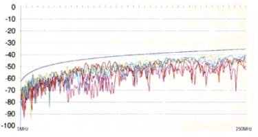
Crosstalk is undesirable signal transmission from one signal pair
to another in close proximity. Crosstalk can cause communication
problems in networks. The most significant characteristic of LAN
cabling performance is crosstalk. High levels of crosstalk will
prevent a LAN from performing properly.
The
NEXT test measures crosstalk by applying a test signal to one signal
pair and measuring the amplitude of the crosstalk signals received
by the other signal pairs. The crosstalk value is computed as the
difference in amplitude between the test signal and the crosstalk
signal as measured on the pair under test, from the same end of
the cable. This difference is called Near End Crosstalk (NEXT) and
is expressed in decibels (dB). Lower NEXT values correspond to better
system performance.
All
signals transmitted through a cable are affected by attenuation,
therefore crosstalk occurring at the far end of a cable contributes
less to NEXT than crosstalk occurring at the near end of a cable.
Power
Sum Near End Cross Talk (PSNEXT)
PowerSum Near End Crosstalk (PSNEXT) is an extension of conventional
NEXT. PowerSum NEXT plays an important role in determining whether
the cabling system is capable of running protocols that utilise
multiple pairs in the same sheath concurrently. There are 6 NEXT
combinations, but only four PowerSum combinations, one each for
the blue, orange, green and brown pairs. PowerSum is determined
mathematically from the six conventional NEXT tests. See the diagram
below for an illustration of the differences between conventional
and PowerSum NEXT.
Attenuation
To Cross Talk Radio(ACR)
ACR (attenuation to crosstalk ratio) is the difference between NEXT
in dB and attenuation in dB. The ACR value indicates how the amplitude
of signals received from a far-end transmitter compare to the amplitude
of NEXT produced by near-end transmissions. A high ACR value means
that the received signals are much larger than the crosstalk. In
terms of NEXT and attenuation values, a high ACR value corresponds
to low NEXT and low attenuation.
Power
Sum ACR(PRACR)
PowerSum ACR is to ACR as PSNEXT is to NEXT. Instead of the ACR
values being measured for all six pair combinations they are calculated
for the four pairs in the cable. Modern protocols utilise more than
one pair to achieve their high bit rates. In situations such as
these more than one signal in each direction could be transmitted
at any one time. PowerSum is a method of testing that ensures that
a cabling system is capable of transmitting a multi-pair protocol.
Equal
Level Far End Cross Talk(ELFEXT)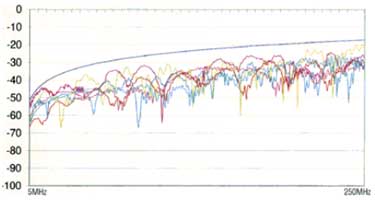
Far End CrossTalk (FEXT) is another new type of test that has been
introduced to ensure modern cabling systems are capable of transmitting
modern protocols. New protocols utilise multiple pairs and the signals
can travel in opposite directions at the same time. It is no longer
sufficient to simply test for Cross Talk at the Near End but a Far
End Cross Talk test must also be completed.
The
test signal is transmitted from one end of the cabling sample and
measured at the other on a different pair. By repeating the tests
on all combinations of pairs in both directions a full evaluation
of FEXT can be derived.
Since
the signal has been attenuated along the length of the cable, that
attenuation is added back to the final measurement to give equal
level FEXT. This adding back of the attenuation provides a relative
measurement of FEXT and allows a true comparison of the level of
received signals at the Far End.
PowerSum
Equal Level Far End Cross Talk(PSELFEXT)
As with all crosstalk measurements (including ACR) there is also
a PowerSum ELFEXT (PSELFEXT). These are calculated values expected
for multi-pair simultaneous full duplex transmissions
Attenuation
Attenuation is the decrease in the strength of a signal over the
length of the cabling link and channel. This is caused by the loss
of electrical energy due to the resistance of the conductors, and
by leakage of energy from the link and channel. This loss of energy
is expressed in decibels (dB). Lower attenuation values correspond
to better link and channel performance. For example, when comparing
the performance of two cables at a particular frequency, a link
and channel with an attenuation of 10 dB performs better than a
link and channel with an attenuation of 20 dB.
Link
and channel attenuation is determined by the cable and cross connect
construction, length and the frequencies of the signals transmitted
through the link and channel. At higher frequencies, skin effect,
inductance and capacitance cause attenuation to increase.
Characteristic
Impedance
Characteristic impedance is the impedance that a link and channel
exhibits if the link and channel were infinitely long. Impedance
is a type of resistance that opposes the flow of alternating current
(AC). A link and channel's characteristic impedance is a complex
property resulting from the combined effects of the link and channel's
inductive, capacitive, and resistive values. These values are determined
by physical parameters such as the size of the conductors, distance
between conductors, and the properties of the cable's insulation
material.
Proper
network operation depends on a constant characteristic impedance
throughout the system's cables and connectors. Abrupt changes in
characteristic impedance, called impedance discontinuities or impedance
anomalies, causes signal reflections, which can distort signals
transmitted through LAN cables and cause network problems.
Return
Loss
Return Loss (RL) is the difference between the power of a transmitted
signal and the power of the signal reflections caused by variations
in link and channel impedance. A return loss plot indicates how
well the link and channel's impedance matches its rated impedance
over a range of frequencies. High return loss values mean a close
impedance match, which results in greater differentiation between
the powers of transmitted and reflected signals. Links and channels
with high return loss values are more efficient at transmitting
LAN signals as less of the signal is lost in reflections.
|


